3 Bit Synchronous Counter Using D Flip Flop
2 Design a 3-bit counter that follows the sequence. We identified it from obedient source.

Solved D Figure A 34 Shows An Asynchronous 3 Bit Up Counter Design A 1 Answer Transtutors
Consider a 3-bit counter with each bit count represented by Q 0 Q 1 Q 2 as the outputs of Flip-flops FF 0 FF 1 FF 2 respectivelyThen the state table would be.
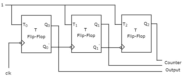
. By applying the same circuit in series we can then divide the frequency by 2 4 and 8. 1-Bit Counter Using D-Flip Flop 1 Angeles_Maila. Unused states 0 2 5 must go to a used.
Both of these flip-flops have a different configuration. A flip flop stores only one bit hence for a 3 bit counter 3 flip flopsn3 are needed to design the counter. You can easily extent this circuit upto 4 bit 5 bit etc.
The counter has an output Z which is high w count is 100. We can find out by considering a number of bits mentioned in the question. By adding flip flops after the 3rd flip flop.
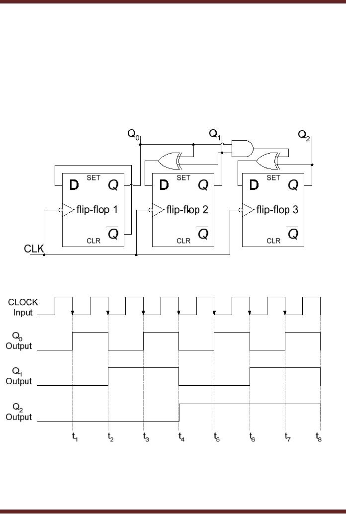
The block diagram of 3-bit Asynchronous binary down counter is similar to the block diagram of 3-bit Asynchronous binary up counter. The expression D 2 Q 2 Q 1 Q 0 thus at intervals t 1 t2 t3 and t8 the output Q2 is set to 0 as D2. If you really know logic gates flip flops and counters you can easily understand how.
Draw the pin configuration of the IC used. 146 3 7 1 4 6 unter that follows the sequence. Design a 3-bit synchronous counter using D-flip flop that has the counting sequence shown in Fig.
Figure 321a D flip-flop based implementation of 3-bit Synchronous Counter. 3-bit synchronous up counter. 146 3 7 146 3.
Ask Question Asked 9 years 1 month ago. We review their content and use your feedback to keep the quality high. Input is at logic 0.
Draw a multisim design of the function by using JK-FF and the 7-segment display and the 7447. Since the counter is of 3. My problem is that it initializes my value with 0 but after that it does not reset entirely on the positive edge of the clock only the first bit is affected.
1 Design a 3-bit synchronous counter using D flip-flops. 3 bit synchronous counter design d flip flop. Who are the experts.
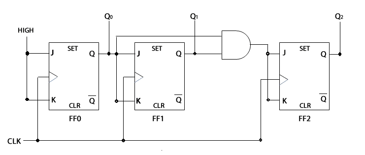
The circuit of the 3-bit synchronous up counter is shown below. I am trying to implement a 4-bit asynchronous counter Ripple counter with synchronous reset. Choose the type of flip flop.
To design a synchronous up counter first we need to know what number of flip flops are required. Bdisplay the counter output using the 7-segment display device. The counter will count when the enable EN is zero and hold when enable is one.
Synchronous up Counter counts the number of clock pulses at its input from minimum to maximum. The structure is that you have a 3-bit state which is the output of the counter and a control signal updown and every clock you transition to a new state. The clock pulse is given for all the flip-flops.
Unused states S5 101 S6 110 S4 011 S7 111 000 S3 100 S1 001 Main sequence ofo Fig. In the first step determine the number of flip flops required. We agree to this nice of Jk Flip Flop Ring Counter graphic could possibly be the most trending topic in imitation of we allocation it in google improvement or facebook.
18 hours agoShow activity on this post. 5 months 3 weeks ago. A single 7474 IC consists of 2 flip flops.
5 months 3 weeks ago Tags. You will find that some steps are fairly easy creating the State Transitio. Above circuit diagram represents a 3 bit Johnson counter using 7474 D flip flop.
Now put it in a feedback from the output to the input of 3 D flip-flops so then at each clock edge the state will be updated. A 3-bit counter consists of 3 flip-flops and has 2 3 8 states from 000 to 111. The D input to each state flipflop is driven by logic that is a function of the previous 3-bit output and the updown input.
This video will show you how to design a synchronous counter using D flip flops. But the only difference is that instead of connecting the normal outputs of one stage flip-flop as clock signal for next stage flip-flop connect the complemented outputs of one stage flip-flop as clock signal for next stage flip-flop. Design a 3-bit synchronous up counter using d flip flops that counts in the sequence 1234.
The basic operation is the same as that of the 2-bit asynchronous binary counter except that the 3-bit counter has eight states due to its three flip-flops. Søg efter jobs der relaterer sig til 3 bit synchronous counter using jk flip flop eller ansæt på verdens største freelance-markedsplads med 21m jobs. Number of states 2 n 23 8 states000 001 010 011 100 101 110 111 Step 2.
My ripple counter is implemented using D flip flop. 3-Bit Synchronous Down Counter Using D-Flip Flop. At intervals t 4 t5 t6 and t7 the output Q2 is set to logic 1 as D2 input is at logic.
This diagram represents both the input and output signals when a feedback loop is applied to a D-Type flip-flop circuit. Reset the circuit to the 000 state. So you need two 7474 ICs for implementing Johnson ring counter.
The logic diagram of the 3-bit asynchronous binary counter using D flip-flops is shown in Figure 11. Initially all the flip flops are cleared. Its submitted by dealing out in the best field.
And two outputs which are either a 3 or 5-bit bus and a terminal counter which is 1 when all bits are 111 or 11111. Its got the two inputs CE and the clock. Up counter can be designed using T-flip flop JK-flip flop with common input D-flip flop.
724637 the design must be done using JK-FF a. Here are a number of highest rated Jk Flip Flop Ring Counter pictures on internet. But Im tasked with making a 3-bit and 5-bit counter out of D-Flip Flops and various logic gates.
Experts are tested by Chegg as specialists in their subject area. Modified 8 years 11 months ago. The original signal clock and the 3 resulting signals will then produce the desired counting effect.
So in this we required to make 3 bit counter so the number of flip flops required is 3 2 n where n is a number of bits. Not really sure where to go from here I have designed in logism a start schematic with a CLK CLR and PRE with 3 D type Flip flops as these are the ones I am required to use but I am unsure where to go from here. Design a 3-bit synchronous irregular counter in the given sequence must be in this sequence.
Designing a 4-bit binary counter.

Bcd Counter Using D Flip Flops
How To Design A 3 Bit Synchronous Counter Using J K Flip Flop That Should Follow The Counting Sequence 7 1 4 5 2 3 0 6 And Repeat Quora

Design A Synchronous Counter Using D Flip Flops Youtube

4 Bit Mod 12 Synchronous Counter Using D Flip Flop Sequential Logic Circuit Digital Electronics Youtube

Synchronous 3 Bit Counter With Negative Edge Triggered Qca Circuit Download Scientific Diagram
D Flip Flop Based Implementation Digital Logic Design Engineering Electronics Engineering

3 Bit Synchronous Up Counter Youtube
Digital Electronics Laboratory
State Table Logic Circuit 3 Bit Binary Counter D Flipflop Computer Science Simplified A Website For Ignou Mca Bca Students For Solved Assignments Notes C Programming Algorithms Cssimplified Com
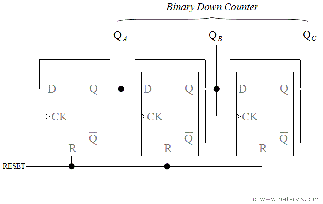
3 Bit Binary Down Counter Using D Flip Flops
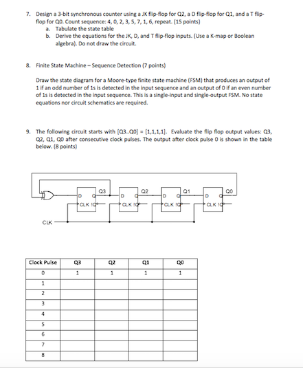
Solved 7 Design A 3 Bit Synchronous Counter Using A Jk Chegg Com
How To Make A 3 Bit D Flip Flop Up Down Counter Quora
How To Make A 3 Bit D Flip Flop Up Down Counter Quora
How To Design A Synchronous Counter Using D Type Flip Flops For Getting The Following Sequence 0 2 4 6 0 Quora
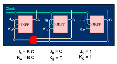
Solved Design Of A 3 Bit Synchronous Counter That Counts Chegg Com
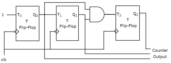

Comments
Post a Comment